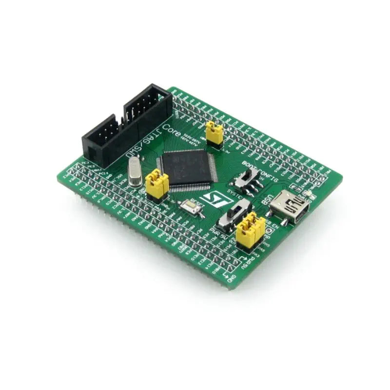
Waveshare Core407V STM32F4 Core Board
Description Waveshare Core407V STM32F4 Core Board Features high-performance STM32F407VET6 MCU Supports diverse communication interfaces Integrates essential USB and power management Provides accessible I/O via pin headers Includes JTAG/SWD for program debugging The Waveshare Core407V STM32F4 Core Board is a compact development platform featuring the STM32F407VET6 microcontroller, designed for initiating application development within the STM32F family. This board integrates essential components such as a USB communication interface, JTAG/SWD programming and debugging interface, clock circuit, and USB power management. It also includes a boot mode selection feature, making it a comprehensive, ready-to-run system. The board is equipped with pin headers on the backside, allowing it to be easily integrated into application boards, serving as the MCU core circuit. All input/output ports are accessible via these pin headers, which are designed with a 2.54mm pitch for compatibility w